The heated intake tube (part number 7200-050) is an accessory for the LI-7200/RS gas analyzer. It warms the intake tube to prevent condensation in the tube and improve the frequency response of water vapor measurements, which is especially important in humid environments. The heated intake tube can be installed on any LI-7200/RS. If your instrument was manufactured before June, 2015, update the software before using the heated intake tube.
What's Included
The heated intake tube kit includes the following components:
| Description | Part Number |
|---|---|
| Heated Intake Tube | |
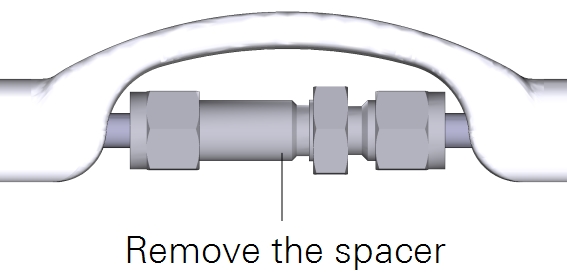
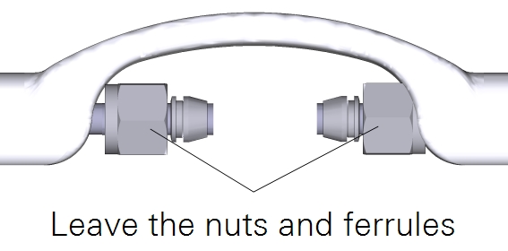
| Swagelok Spacer with Nuts and Ferrules | |
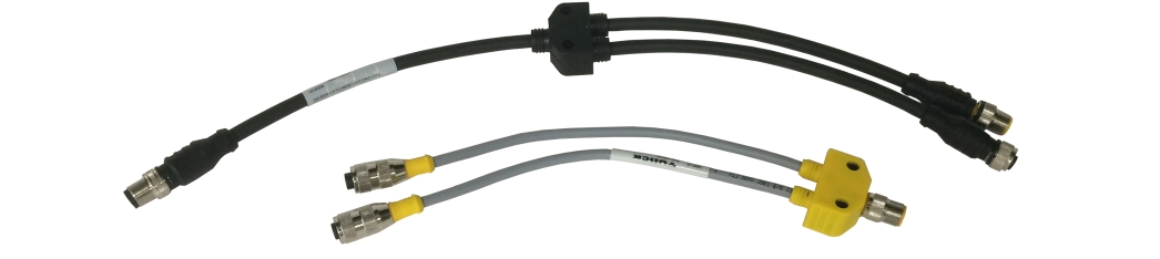
| Accessory T-splitter (older version) | 392-10502 |
| Accessory Cable Splitter (new version) | 392-17153 |
| Power Supply Splitter Cable | 392-15382 |
| Power & Communication Adapter Cable | 392-15383 |
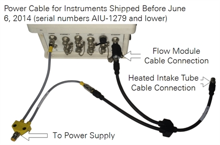
If your instrument was manufactured before June 6, 2014, you'll need the Power Supply Splitter and Junction1 (part numbers 392-15382 and 392-15383 respectively)
Installing the Heated Intake Tube
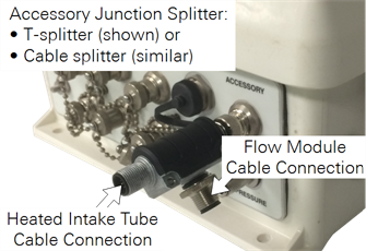
All LI-7200/RS instruments need the accessory junction splitter to be installed on the LI-7550, so install it on the accessory connector. Early heated intake tubes have a T-shaped splitter (392-10502); later models have a splitter cable (392-17153). Install the splitter provided with your intake tube.
Important: Tighten the cable connectors securely. After the connectors get snug, wiggle and tighten them again to ensure a weather-tight connection.
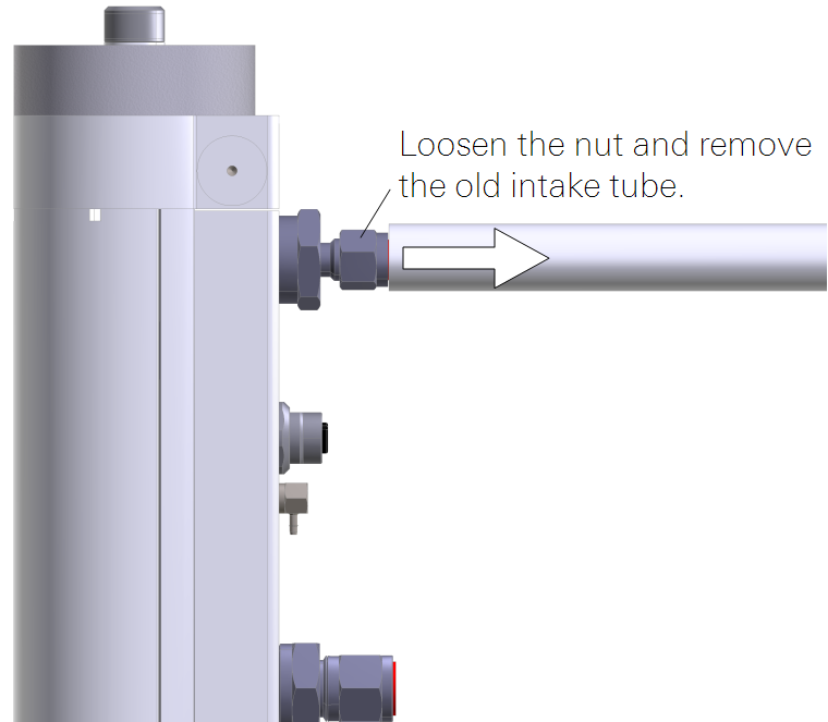
Early instruments are equipped with a 3/8" inlet fitting. It should be replaced with the ¼" fitting before installing the tube.
- Remove the old intake tube (if installed).
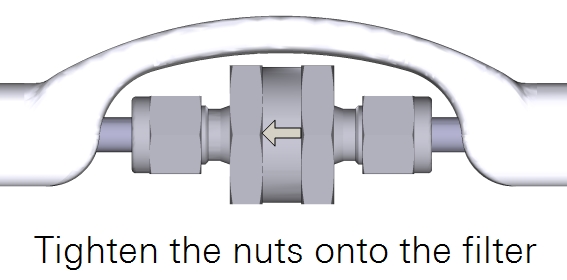
- Install the particulate filter (optional). Air should flow in the direction indicated on the filter.
- Install the tube in the analyzer head.
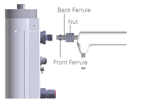
- Tighten all fittings securely.
- Attach the intake tube to a secure mount so that the analyzer is not bearing its weight.
- Connect the intake tube cable.
- It connects to the accessory junction splitter.
- Secure the cables so that cable junctions are not bearing their weight.
Note: The heated intake tube is not flexible. Do not bend it.
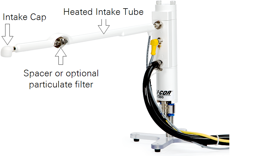
Installing the Intake Cap
The intake cap kit includes the following components:
- Intake Cap (includes screen and hose clamp).
- Spare screen, retaining ring, and hose clamp.
The intake cap attaches to the standard ¼" diameter intake tube (part number 9972-053) and heated intake tube. To install the intake cap:
- If necessary, remove the old cap and all of its components from the intake tube.
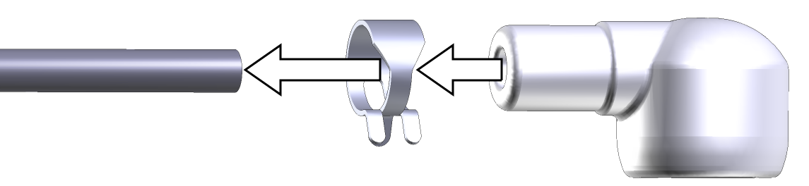
- Place one hose clamp over the intake tube and slide the new intake cap over the stainless steel intake tube until it stops.

- The intake tube should extend ~1 inch (2.54 cm) into the cap.
- Using a pliers, grasp the hose clamp to expand it. Slide it over the inlet cap as shown and release it.
Note: Do not expand the hose clamp more than necessary. Doing so can permanently deform the clamp.
Configuring the Intake Tube
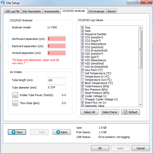
In the gas analyzer software, under Site Setup, enter the dimensions of the intake tube.
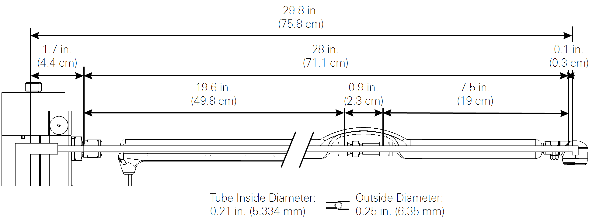
Dimensions
Tube length (cm) (mandatory): LI-7200/RS intake tube length, in centimeters.
Tube diameter (mm) (mandatory): LI-7200/RS intake tube inside diameter, in millimeters.
- Tube length: 71.1 cm (enter the total length)
- Tube inside diameter: 5.33 mm
If you are using the Heated Intake Tube, configure the power setpoint.
Power Setting
If you are using the Heated Intake Tube, configure the power setpoint. Click the LI-7200/RS menu and select Intake Tube... and set the power setpoint.
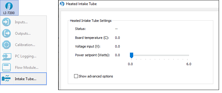
- Status: Indicates whether the heated intake tube is detected [OK, Unknown, or None].
- Board temperature (C): Temperature measured on the heated intake tube circuit board.
- Voltage input (V): Voltage measured at the heated intake tube.
- Power setpoint (Watts): Desired power to be delivered to the heated intake tube. Typically 4 W. In tropical and other extremely humid environments, use 6 W. A setting as low as 0.5 W can prevent condensation in the tube, but 4 W will improve frequency response.
- Show advanced options: Use this if you need to upload new firmware to the heated intake tube.
Heated Intake Tube Specifications
Input Voltage: 10.5 - 30 V
Total Output Wattage: 0.1 W to 6 W (Heat density ratio: 2:1 short tube to long tube)
Operating Temperature Range: -40 °C to 50 °C
Data Communication Protocol: RS-485
Intake Tube Inside Diameter: 5.33 mm (0.21”)
Intake Tube Outside Diameter: 6.35 mm (0.25”)
Intake Tube Length: 71.1 cm (28”)
Cable Length: 5 m (16.40’)
Intake Tube Weight: 0.54 kg (1.2 lbs)