LI-7200/RS Air Intake and Dust Filter
This document describes the intake cap and dust filter for the LI-7200/RS. The intake cap (part number 9972-072) is designed to minimize water vapor and CO2 frequency attenuation. The dust filter (part number 9972-073) helps prevent dust and pollen from entering the LI-7200/RS optical cell.
Installing the Air Intake
The intake cap kit includes the following components:
- Intake Cap (includes screen and hose clamp).
- Spare screen, retaining ring, and hose clamp.
The intake cap attaches to the standard ¼" diameter intake tube (part number 9972-053) and heated intake tube. To install the intake cap:
- If necessary, remove the old cap and all of its components from the intake tube.
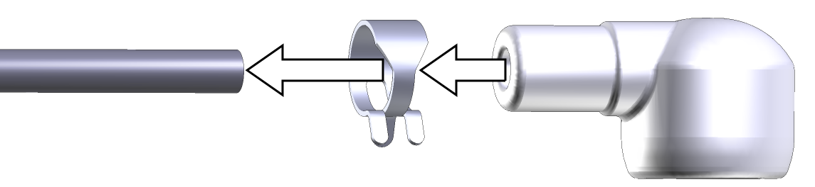
- Place one hose clamp over the intake tube and slide the new intake cap over the stainless steel intake tube until it stops.

- The intake tube should extend ~1 inch (2.54 cm) into the cap.
- Using a pliers, grasp the hose clamp to expand it. Slide it over the inlet cap as shown and release it.
Note: Do not expand the hose clamp more than necessary. Doing so can permanently deform the clamp.
Cleaning the Intake Cap and Screen
To clean the cap and screen, remove the intake cap assembly and back-flush it with compressed air or water. You can immerse the intake cap assembly in boiling water for a few minutes or soak it in an ultrasonic water bath. Usually, you should not have to remove the screen from the cap. If you do need to remove the screen:
- Insert a small screwdriver between the screen and intake cap.
- Use caution to avoid damaging the cap and deforming the screen.
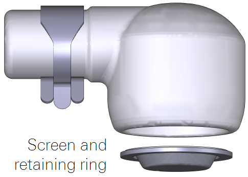
- Carefully pull the screen out of the cap.
- Assembly is the reverse of removal. Be sure the screen is seated fully in the cap.
Dust Filter
The dust filter (part number 9972-073) is a Swagelok® 2-micron filter that will reduce the amount of dust that enters the gas analyzer optical cell. Under normal conditions, the filter should extend the amount of time that can pass before you need to clean the optical cell. Use the filter in environments that have airborne dust and pollen that can contaminate the optical cell.
Important: The filter does not completely eliminate the need to regularly clean the optics. Regular cleaning is required in order to prevent measurement drift that can occur when certain kinds of contaminants accumulate on the cell windows.
- The filter will increase the power requirements of your system. As the filter becomes dirty, the flow module will use more power to maintain the same flow rate.
- The filter may affect H2O frequency response, especially when it is dirty. (This can be addressed with additional frequency response corrections.)
- The effectiveness of the filter depends upon the site conditions, overall level of dust in the air, and the characteristics of the dust (fine vs. coarse dust particles).
The dust filter includes:
- Swagelok filter with two compression fittings.
- Two inch (5.08 cm) by ¼ inch stainless steel intake tube extension.
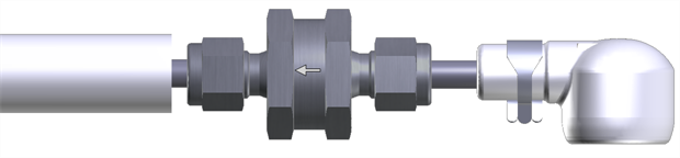
The dust filter installs between the end of the intake tube and the intake cap. To install it:
- Remove the intake cap.
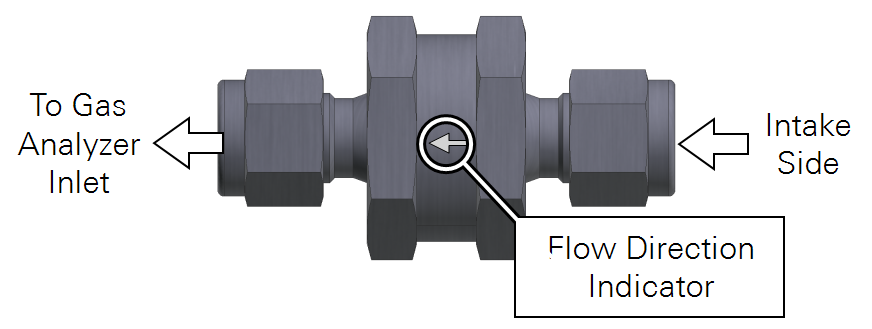
- Carefully observe the flow arrow indicator on the filter. Air should flow in the direction of the arrow.
- Remove the compression fitting from the intake side of the filter.
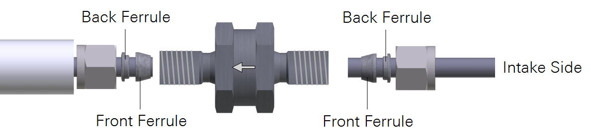
- Install the nut, front ferrule, and back ferrule over the short stainless steel pipe.
- Be sure the tube is fully seated in the filter. Tighten the fitting to hand tight, then about ½ turn more using 9/16" and 1" wrenches.
- Install the nut, front ferrule, and back ferrule on the intake tube.
- Install the inlet cap.
Maintaining the Filter
How do you know when to clean the filter? Dust will accumulate in the filter over time. The rate of dust accumulation will depend upon the amount of dust in the air and the particle size of dust. Therefore, it is difficult to predict exactly when the filter should be cleaned.
As dust builds up in the filter, the flow module will use more power to maintain the flow rate. So, the best indicator of the filter status is a change in the power required to run the flow module. When you install a new filter, record the Flow Drive (%), or log that variable with your data. Over time, compare the flow drive % with the initial value. The % will increase as the filter becomes clogged, indicating that the pump must work harder to move air through the filter.
Clean the filter before the Flow Drive (%) exceeds 90%.
Cleaning: If possible, use an ultrasonic water bath, then back-flush the filter with compressed air and allow the filter to dry before reinstalling. Otherwise, immerse the filter in boiling water for a few minutes or soak it over night and then back-flush it with compressed air. As a good practice, clean the intake cap whenever you clean the filter.
The ferrules/compression fittings do not need to be removed from the intake tubes when the filter is removed. They can be reused.
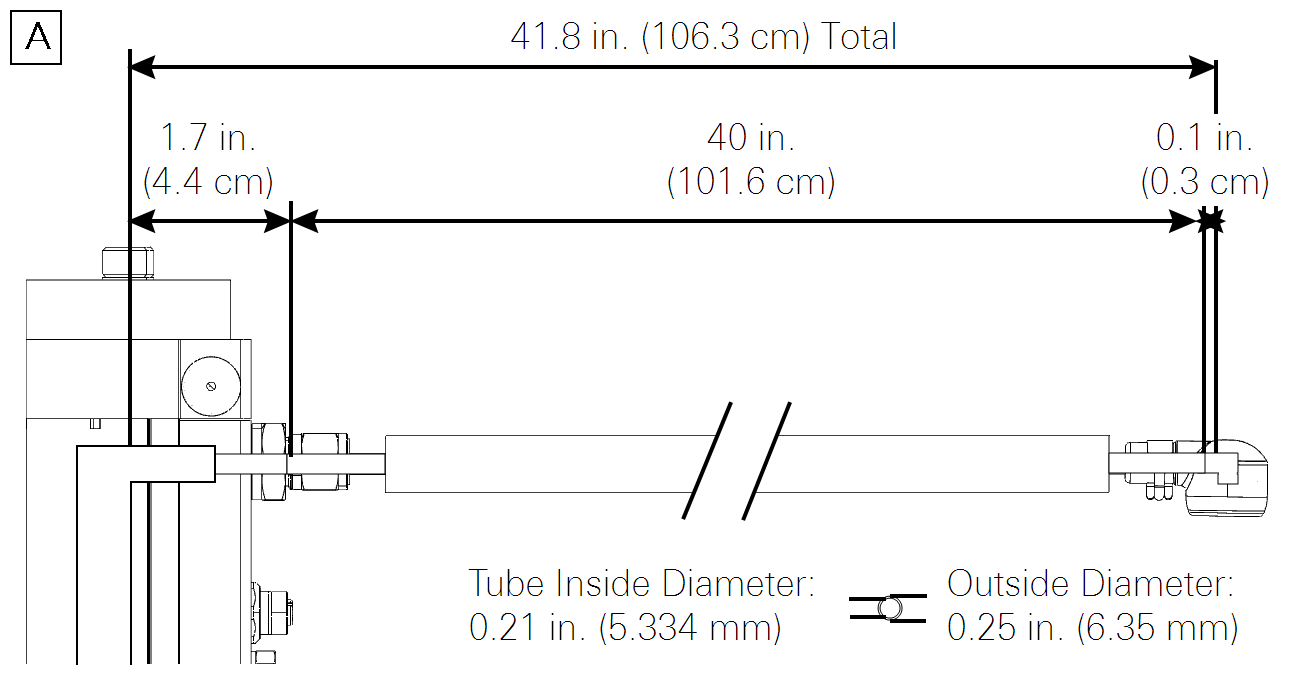
Insulated Intake Tube Specifications
Outside Diameter: 0.25" (6.35 mm)
Inside Diameter: 0.21" (5.334 mm)
Wall Thickness: 0.020" (0.51 mm)
Length: 40" (101.6 cm)
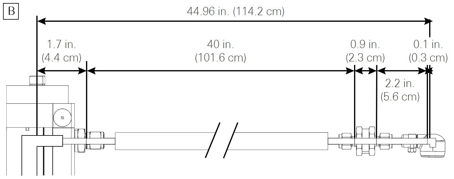
Intake tube path length when assembled: 102 cm
Intake tube path length with filter: 106.5 cm
Material: 304 Stainless Steel