Logging LI-720 Data to a Campbell Scientific Datalogger
Authors: LI-COR, Inc.
Correspondence: envsupport@licor.com
Published: 2024
Instruments: LI-720
Keywords: CO2 flux, logging data, datalogger, CR1000, CR3000, CR5000
Abstract
You can record data from the LI-720 on dataloggers that support the SDI-12 protocol. This section summarizes the configuration and includes links to simple programs for logging data from the LI-720 to a Campbell Scientific® device. The programs will read data from the LI-720 only. If you want to add the LI-720 to an existing program Campbell Scientific can provide the technical assistance that is required for modifying datalogger programs beyond what is described here.
Requirements for this tutorial
The following items are required to complete this tutorial.
- LI-720 Evapotranspiration Sensor
- Personal Computer (Windows OS)
- Campbell Scientific datalogger
- PC400 software from Campbell Scientific:
campbellsci.com/downloads/pc400 - Program (5-minute periods of all variables for testing):
licor.app.boxenterprise.net/s/mnbvi1ho04fohqz5md9lzjclxaejwik8 - Program (30-minute periods of all variables):
licor.app.boxenterprise.net/s/fwonls2r3u7ckffrhzftqf2vlf0hta82
Wire assignments

The LI-720 is powered over the brown wire (9 to 33 VDC). Data are transferred over the blue DATA wire. The black wire connects to ground. Some SDI-12 power supplies may not provide enough current to power up the LI-720. If you observe continuous power cycling, consider powering the LI-720 directly from the datalogger power supply.
Default address
All LI-720s leave LI-COR with an address of 0. The address can be changed with the A command. Multiple LI-720s can be connected to a single SDI-12 bus, but each LI-720 requires a unique address.
The trigger command
The LI-720 is designed to respond to trigger (XT) commands on a schedule. Trigger options and the expected results are described below.
Trigger on a schedule with the XT command
In triggered mode, the LI-720 starts up and begins recording raw data to its volatile memory. When the LI-720 receives an XT command, it computes results from data in the volatile memory and starts recording new raw data to the volatile memory. These results are reported in response to a C then D command until new results are available – a few seconds after the LI-720 receives another XT command (see Trigger on a schedule in Figure 2).
Note: We recommend Trigger on a schedule for deployments. In this mode, the datalogger sends the XT command to start a measurement period and the C command followed by the D command to request results. This gives you control over the measurement time period and aligns results to the datalogger clock.
We recommend sending the XT command every 30 minutes, but you can choose any time period between 5 and 60 minutes. The time period for computing results is defined by the time period between XT commands sent by the datalogger.
Trigger once
Note: Trigger once is for testing or a fallback if the trigger is not received.
If the LI-720 receives an XT command but does not receive another, it will compute results when it has recorded 36,000 data points, which is around one hour (see Trigger once in Figure 2). If triggered only once, the subsequent measurements will gradually drift from the datalogger clock.
No trigger
Note: Use No trigger for testing only.
The LI-720 operates in untriggered mode unless it receives a trigger command. In untriggered mode, the measurement period does not have explicit alignment with a clock. Instead, the LI-720 begins recording raw data to its volatile memory almost immediately after it is powered on. After it has recorded 18,000 data points (about 30 minutes of data), it computes results for that time period. These results are reported until the next results are ready 18,000 data points later (see No trigger in Figure 2).

Common commands
The following commands are supported by the LI-720.
- ? – Get the sensor address.
- I - Get sensor information.
- A – Set the sensor address.
- XT – Trigger to start a new measurement period.
- C – Concurrent measurements allow a large number of variables to be sampled and sampling of other sensors while the concurrent data request is being fulfilled.
- D - Send data (not required by Campbell data loggers, but may be needed by other loggers).
Send the XT command to trigger a new measurement period and then send the C command to start a concurrent measurement. For some devices, and send the D command to request data.
Sample program
The program in Listing 1 is for a Campbell Scientific datalogger.
Listing 1. Sample program that logs all LI-720 variables to Campbell Scientific data logger. Variable names are truncated for simplicity.
'LI-720 simple logger program'
'Rev: 1.0'
'Date May 07, 2025'
'Author: LI-COR, Inc.'

Public LI720F(56)
Alias LI720F(1) = year_gmt
Alias LI720F(2) = month_gmt
Alias LI720F(3) = day_gmt
Alias LI720F(4) = hour_gmt
Alias LI720F(5) = minute_gmt
Alias LI720F(6) = second_gmt
Alias LI720F(7) = FCO2
Alias LI720F(8) = FH2O
Alias LI720F(9) = ET
Alias LI720F(10) = LE
Alias LI720F(11) = H
Alias LI720F(12) = TAU
Alias LI720F(13) = samp_cnt
Alias LI720F(14) = seq
Alias LI720F(15) = wind_dir
Alias LI720F(16) = wind_spd
Alias LI720F(17) = head_avg
Alias LI720F(18) = u_sig
Alias LI720F(19) = v_sig
Alias LI720F(20) = w_sig
Alias LI720F(21) = tson_sig
Alias LI720F(22) = tilt
Alias LI720F(23) = flux_qc
Alias LI720F(24) = ustar
Alias LI720F(25) = mo_length
Alias LI720F(26) = t_sonic
Alias LI720F(27) = tair_sonic
Alias LI720F(28) = co2_mf
Alias LI720F(29) = h2o_mf
Alias LI720F(30) = abs_hum
Alias LI720F(31) = rh_avg
Alias LI720F(32) = svp
Alias LI720F(33) = vpd
Alias LI720F(34) = pa_avg
Alias LI720F(35) = tair_avg
Alias LI720F(36) = tdew
Alias LI720F(37) = par
Alias LI720F(38) = instr_pwr
Alias LI720F(39) = input_V
Alias LI720F(40) = diag
Alias LI720F(41) = rssi_avg
Alias LI720F(42) = u_rec
Alias LI720F(43) = v_rec
Alias LI720F(44) = w_rec
Alias LI720F(45) = ts_rec
Alias LI720F(46) = co2_rec
Alias LI720F(47) = h2o_rec
Alias LI720F(48) = ta_rec
Alias LI720F(49) = pa_rec
Alias LI720F(50) = rh_rec
Alias LI720F(51) = par_rec
Alias LI720F(52) = altitude
Alias LI720F(53) = latitude
Alias LI720F(54) = meas_htz
Alias LI720F(55) = can_htz
Alias LI720F(56) = north_offst

Units year_gmt = YYYY
Units month_gmt = MM
Units day_gmt = DD
Units hour_gmt = HH
Units minute_gmt = MM
Units second_gmt = SS
Units FCO2 = umol/m^-2/s
Units FH2O = mmol/m^-2/s
Units ET = mm
Units LE = W/m^2
Units H = W/m^2
Units TAU = kg/m/s^-2
Units samp_cnt = count
Units seq = count
Units wind_dir = degrees
Units wind_spd = m/s
Units head_avg = degrees
Units u_sig = m/s
Units v_sig = m/s
Units w_sig = m/s
Units tson_sig = C
Units tilt = degrees
Units flux_qc = dimensionless
Units ustar = m/s
Units mo_length = m
Units t_sonic = C
Units tair_sonic = C
Units co2_mf = umol/mol
Units h2o_mf = mmol/mol
Units abs_hum = g/m^-3
Units rh_avg = %
Units svp = KPa
Units vpd = KPa
Units pa_avg = KPa
Units tair_avg = C
Units tdew = C
Units par = umol/m^-2/s
Units instr_pwr = W
Units input_V = V
Units diag = dimensionless
Units rssi_avg = %
Units u_rec = count
Units v_rec = count
Units w_rec = count
Units ts_rec = count
Units co2_rec = count
Units h2o_rec = count
Units ta_rec = count
Units pa_rec = count
Units rh_rec = count
Units par_rec = count
Units altitude = m
Units latitude = degrees
Units meas_htz = m
Units can_htz = m
Units north_offst = degrees

DataTable (fluxdata,True,48)
    DataInterval(0,5,Min,10)
    Sample(56,LI720F,IEEE4)
EndTable

BeginProg
  Scan(5,Min,1,0)
    SDI12Recorder(LI720F,C3,0,"XT!",1.0,0)
    SDI12Recorder(LI720F,C3,0,"C!",1.0,0)
    CallTable fluxdata
  NextScan
EndProg
Reading the serial output
The high-speed serial output can be recorded to a data logger. Data are transmitted over the TX+ lead, which connects to an RX+ terminal on a data logger.

| Wire color | Function | Connects to |
|---|---|---|
| Blue | SDI-12 Data | SDI-12 Data |
| Black | GND | GND |
| Brown | Power | Power |
| Gray | RX+ | TX+ |
| White | TX+ | RX+ |
Data are transmitted at 115200 baud. All variables are transmitted as text. You will need to configure the data logger to record the data.
Mounting options
Horizontal cross bar
The LI-720 can be attached to a standard ¾" crossover fitting or any other fitting with a 1" opening. Suitable crossover fittings (¾" × 1") are available from LI-COR (part number 259-13276).

Tighten set screws with a 5/32" or 4 mm hex key to 22 N-m (16 ft-lbs). If no torque wrench is available, tighten each set screw until it contacts the pipe, then ¼ turn more.
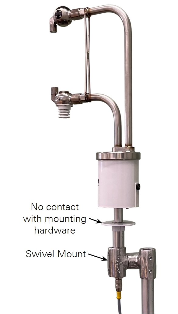
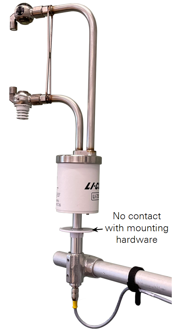
Vertical mast
For a stand-alone installation, the LI-720 can be attached to a T-post and vertical mast, like a piece of pipe. The LI-720 can attach to a pipe using a swivel mount (Figure 4).
If you are using a T-post in soft or saturated soils, check the installation regularly to ensure that the post does not shift over time. Use guy wires for additional stability.