


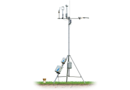
Using the Gill WindMaster/Pro in Eddy Covariance Systems
This document describes how to use the Gill WindMaster and WindMaster Pro in LI-COR eddy covariance systems. The topics covered are installing the anemometer at your site, connecting the anemometer to the SmartFlux 2 or 3 System, and configuring software for the eddy covariance site setup.
Important: Be sure to read and understand the documentation provided with the sonic anemometer.
Installing the anemometer and analyzer
The sonic anemometer should be mounted to the anemometer mounting post with three nuts, washers, and bolts. The mounting post attaches to the tripod or tower with a cross-over fitting.
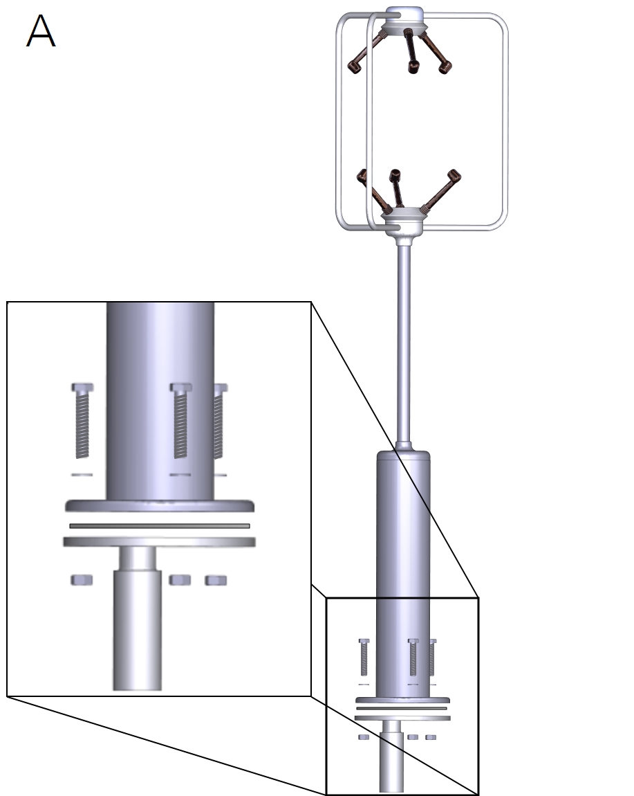
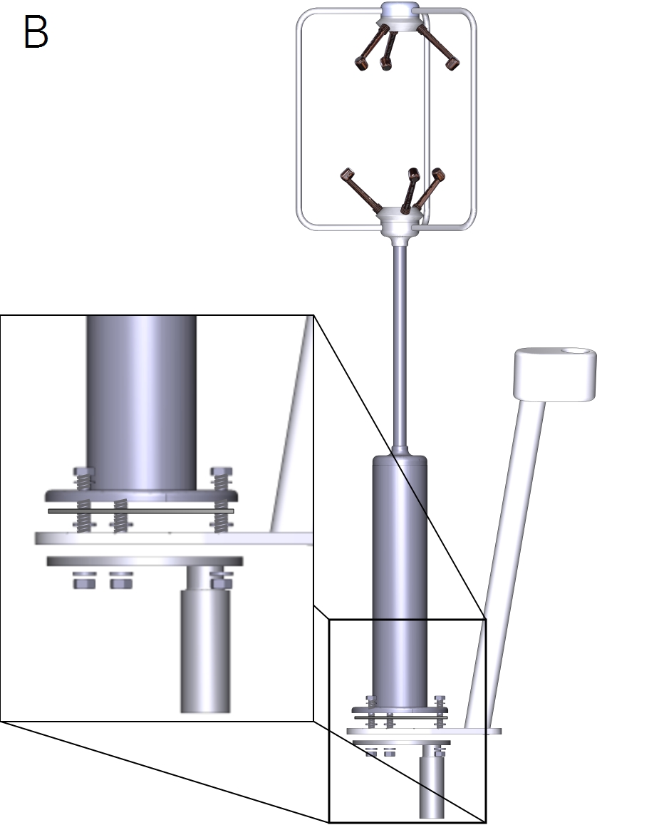
Orientation, horizontal offsets, and vertical offset
Mount the anemometer with the north spar facing north, and then rotate it so that one spar is oriented downwind from the prevailing wind direction.
Measure and record the North offset and height.
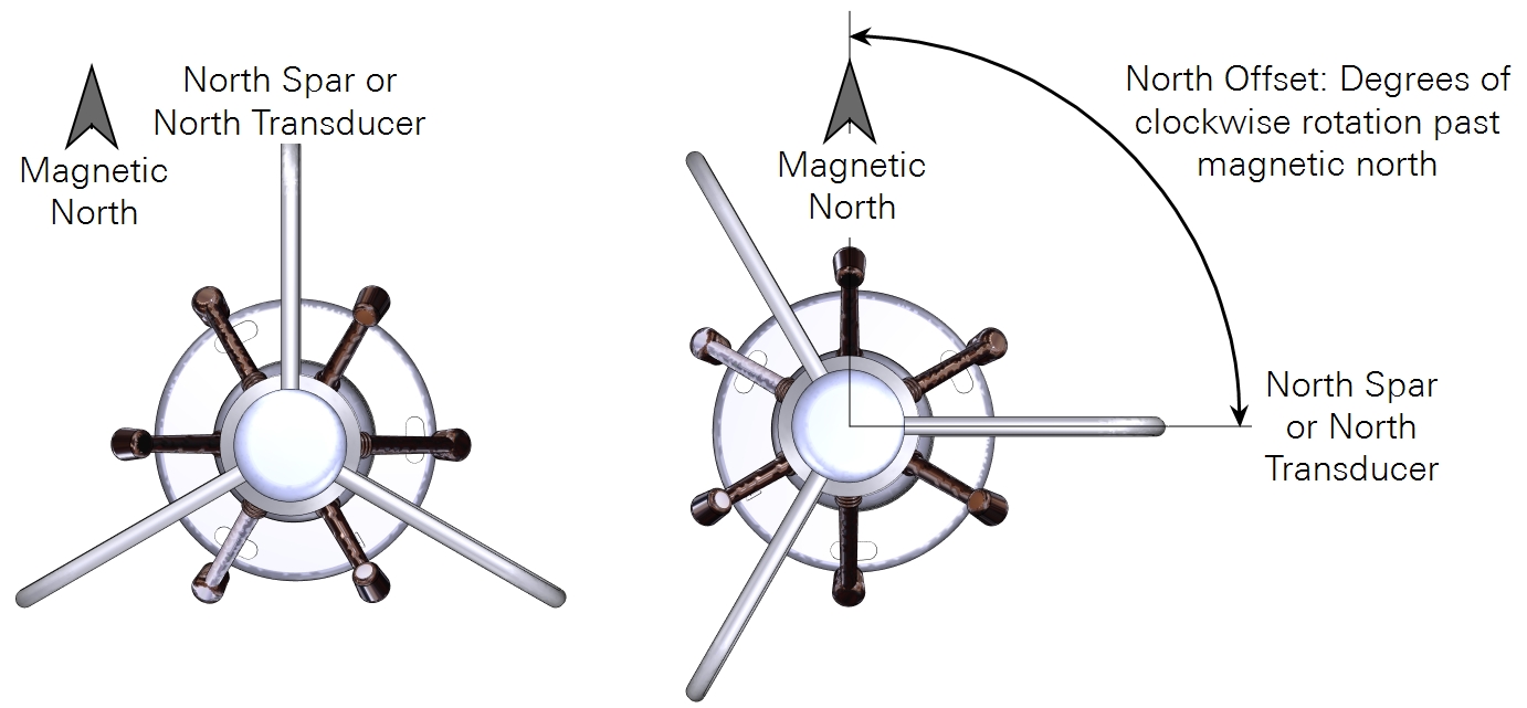
- North offset (°): The degrees of clockwise rotation from magnetic north.
- Height (m): The distance between the ground and the center of the anemometer sample volume.
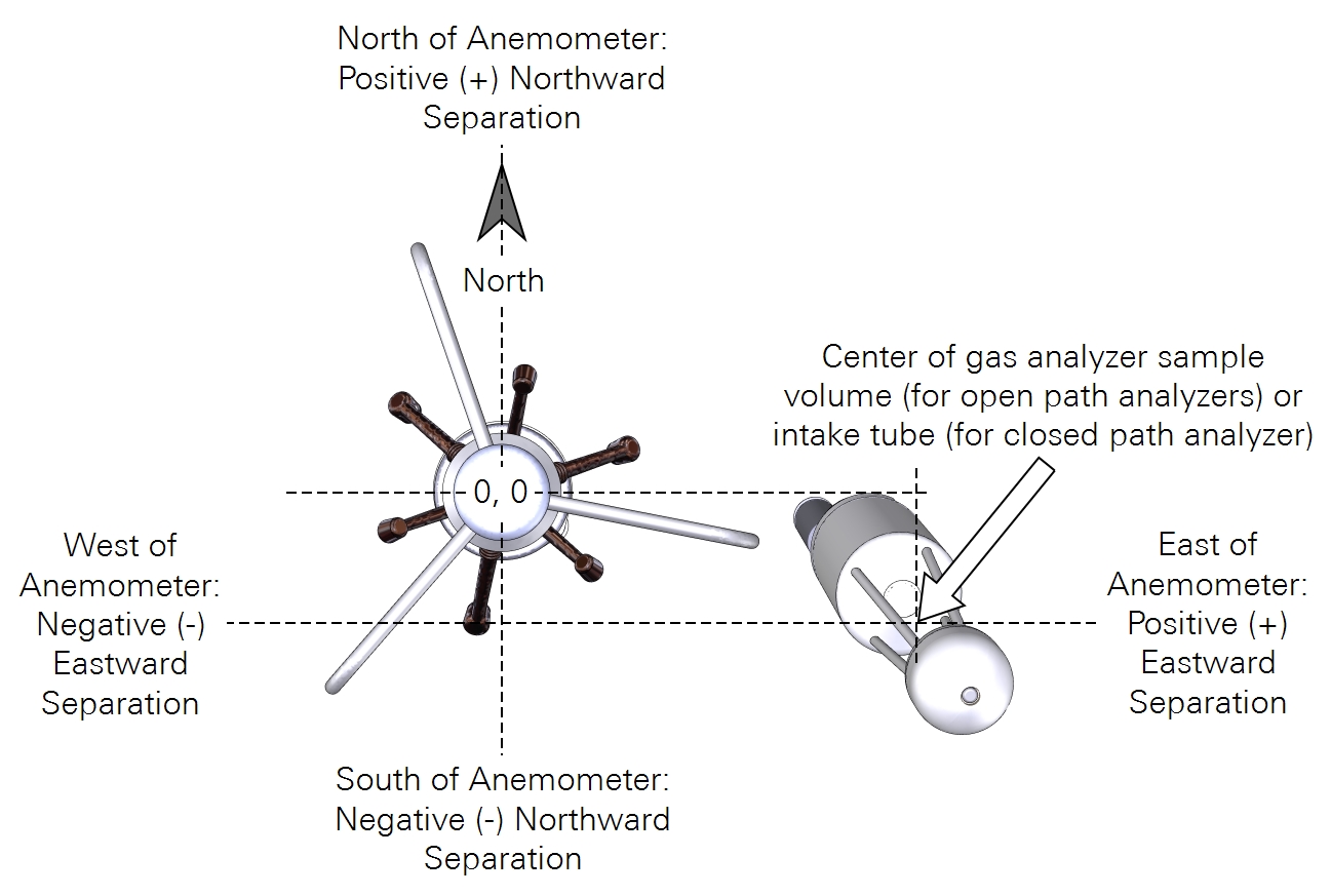
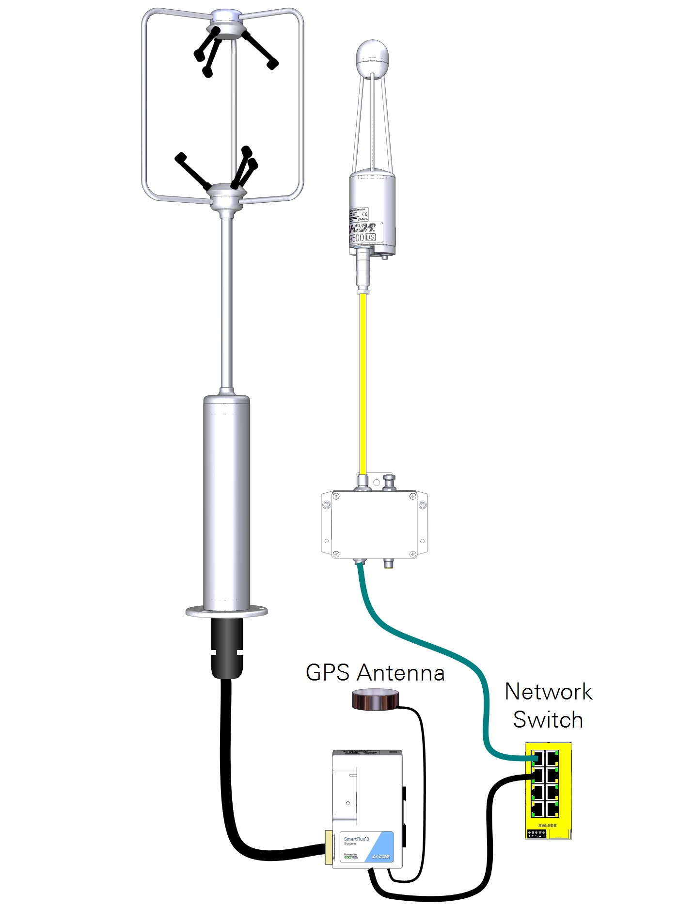
Horizontal separation distances (Figure 3) are measured in a Cartesian coordinate system, which EddyPro® uses to determine the distance between the gas sample and the anemometer. The center of the anemometer is the center (0, 0) of the coordinate system. Distances from the anemometer are provided along the north-south and east-west axes. The sensor head or air inlet should be 10-20 cm from the anemometer in the horizontal plane.
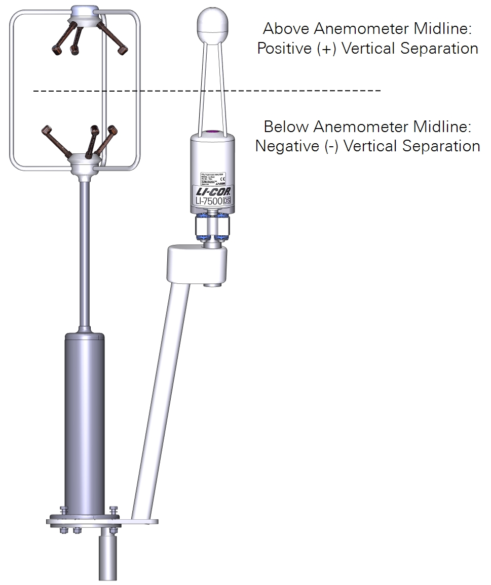
For deployments that are close to a plant canopy, the center of the analyzer and sonic anemometer should be at equal heights, as shown in Figure 4. If mounted over 15 m above ground level, horizontal and vertical sensor separation can be as large as 30-50 cm. Measure and record the horizontal and vertical separation distances.
- Northward Separation (cm): North (positive values) or south (negative values) distance between the sample path or intake and the anemometer.
- Eastward Separation (cm): East (positive values) or west (negative values) distance between the sample path or intake and the reference anemometer.
- Vertical Separation (cm): Vertical distance between the sample path or inlet and the reference anemometer. Negative if the center of the analyzer or the inlet is below the center of the reference anemometer sample volume; positive if the inlet is above.
Connecting to the SmartFlux 2 or 3 System
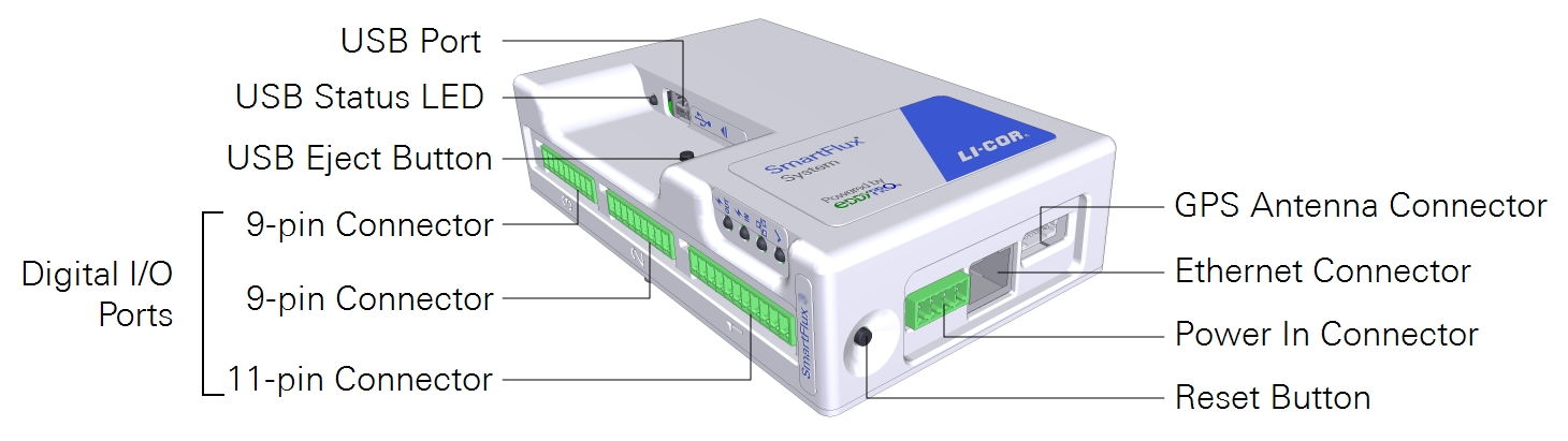
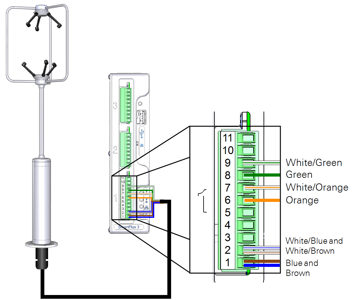
The WindMaster/Pro are automatically configured by the SmartFlux System when connected. The anemometer cable connects to port 1, 2, or 3 on the SmartFlux System (port 1 shown). Port 1 accepts 11-pin and 9-pin terminal strips. Ports 2 and 3 accept 9-pin terminal strips.
| SmartFlux Terminal | SmartFlux Label | Wire Color |
|---|---|---|
| 9 | RS-422/485 RX- | White/Green |
| 8 | RS-422/485 RX+ | Green |
| 7 | RS-422/485 TX- | White/Orange |
| 6 | RS-422/485 TX+ | Orange |
| 2 | Power to Anemometer (-) | White/Blue and White/Brown |
| 1 | Power to Anemometer (+) | Blue and Brown |
Important: Disconnect the power supply to the SmartFlux System before connecting anemometer cables.
Configuring the eddy covariance system
Several things are required: sonic anemometer information and gas analyzer information, and a few additional settings.
Enter sonic anemometer information
Settings cannot be changed while datalogging is active, so stop logging before altering the settings.
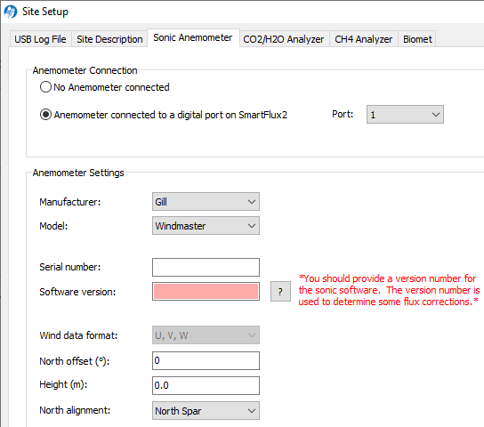
In the gas analyzer PC software, click Site Setup > Sonic Anemometer tab, and select Anemometer connected to a digital port on the SmartFlux 2 or 3 System.
- Port: The port on the SmartFlux system that the anemometer is connected to (1 in this example).
- Manufacturer: Gill.
- Model: WindMaster or WindMaster Pro.
- Serial Number: Automatically populated.
- Software Version: The anemometer software version.
- Wind Data Format: U, V, W.
- North Offset: Degrees clockwise of magnetic North. Measured at the site (see Figure 2).
- Height: Distance of the anemometer sample volume above the ground. Measured at the site.
- North Alignment: A setting in the anemometer software. Either North Spar of North Transducer.
Enter gas analyzer information
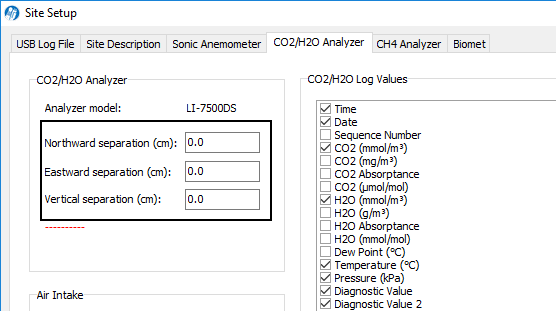
The following information is required:
- Northward Separation (cm): Measured at site (Figure 3).
- Eastward Separation (cm): Measured at site (Figure 3).
- Vertical Separation (cm): Measured at site (Figure 4).
Additional system settings
Although not related to the sonic anemometer, configure the following settings to finish configuring the eddy covariance system. Under Site Setup > USB Log File > USB Log File Options, set the following:
- Log Rate (Samples per Second): 10.0 (or higher).
- File Duration: 30 minutes.
Under Site Setup > Site Description, set the following:
- Site Name: A name of your choice.
- Station Name: A name of your choice.
- Canopy Height (m): The distance between ground level and the top of the plant canopy.
- Check Use SmartFlux GPS coordinates.
At this point, you've configured the minimum required settings to log complete eddy covariance data sets with an LI-7500A/RS/DS. There are additional settings to configure if you are using an LI-7200/RS, a biomet system, or an LI-7700, or if you want to process data using EddyPro Advanced settings. These are described in corresponding product documentation.
Connecting to a Computer
You can connect the anemometer to a computer to view the firmware version and settings for troubleshooting.
Important: Do not leave the USB cable connected to the anemometer during normal use. Failure to disconnect the cable may result in communication problems and data loss.
Use the suitable version of Wind software from Gill or a terminal program such as Tera Term. To connect the anemometer to a computer, attach bare leads of the USB-to-RS-422 adapter cable (392-16348) to bare leads on the anemometer cable. You can insert pairs into a single terminal in a terminal strip, twist them together, or connect them with wire nuts. To power the anemometer, connect the black lead from the USB-to-RS-422 adapter cable and the power leads from the anemometer cable to the Power Out terminals on the SmartFlux System.
The USB-to-RS-422 adapter cable requires a VCP driver, which you can download from www.ftdichip.com.
| USB Cable | connects to | Anemometer Cable |
|---|---|---|
| White (RX-) | connects to | White/Green (TX-) |
| Yellow (RX+) | connects to | Green (TX+) |
| Red (TX-) | connects to | White/Orange (RX-) |
| Orange (TX+) | connects to | Orange (RX+) |
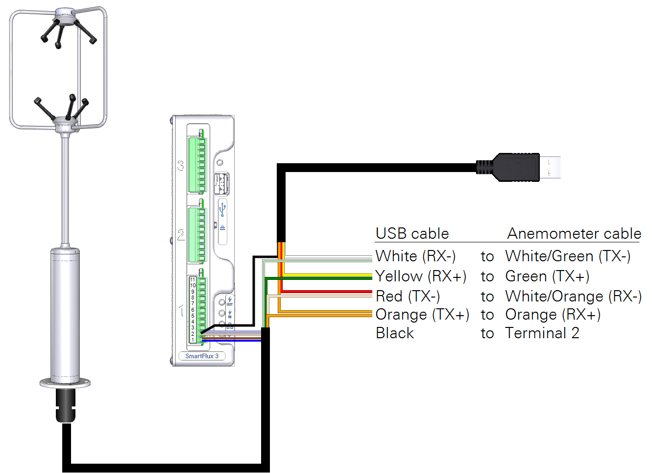
| USB Cable | Anemometer Cable | connects to | SmartFlux |
|---|---|---|---|
| Black (GND) | White/Blue | connects to | Terminal 2 (Power -) |
| n/a | White/Brown | connects to | Terminal 2 (Power -) |
| n/a | Blue | connects to | Terminal 1 (Power +) |
| n/a | Brown | connects to | Terminal 1 (Power +) |