Although LI-COR® provides cellular communication systems that are certified for many regions of the world, you may need to provide your own cellular modem in some situations. If you provide your own cellular modem (referred to as gateway henceforth), this technical note will help you configure the cellular gateway and instruments in your LI-COR eddy covariance (EC) system. For areas without cellular service, satellite options are also available from LI-COR.
Gateway Specifications
The basic specifications for compatible cellular gateways are given below.
- Operating temperature and humidity range suitable for outdoor environments.
- Ethernet socket (female RJ45 terminal).
- TCP/IP communication and port forwarding (DNAT).
- Input voltage range compatible with power supply at site.
To use your modem, the modem must fit in a 20.3 cm x 15.2 cm x 10.2 cm space with room to connect the antenna, power, and Ethernet cables.
Data Plan Requirements
You must arrange a data plan with a cellular service provider that has coverage at your station.
- The cellular service provider should provide a public static IP address.
- The data plan must support machine-to-machine (M2M) communication.
- If a public IP address is not available, you can get data service through a mobile virtual network operator (MVNO).
- If you get a dynamic IP address, use a Dynamic Domain Name Server (DDNS) to resolve the IP address.
| Sensors | Files to Transfer | Data Plan |
|---|---|---|
| Basic EC System | Status Reports and Final Flux Results | <1GB per month |
| Basic EC System | Raw Data | <2GB per month |
| EC System with LI-7700 or Biomet System | Raw Data | <3GB per month |
Your data plan should cover the amount (GB) of data that you will transfer over the cellular network. For example, do you want to view small summary files showing the overall performance of your system, or do you want to transfer all your raw data files over the cellular network?
Cellular Communication Components
For a station that includes a LI-COR Biomet Enclosure or Systems Enclosure, we recommend the components indicated in Table 2. Some will be included with your communication system, if acquired from LI-COR.
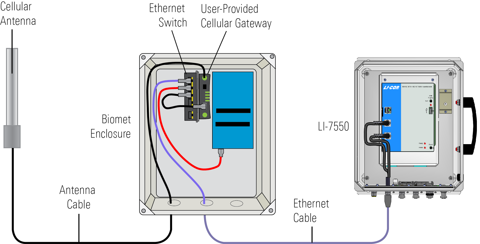
The bracket is used to mount the modem and Ethernet switch inside the biomet system enclosure. It is specific for AirLink® LS300, but you can mount any modem with zip ties, adhesive mounting tape, or adhesive hook-and-loop; or install a DIN-mountable modem and switch to a segment of DIN rail (part number 6579-023).
EC System Network Configuration
Set unique IP address for each instrument in your system so it is compatible with your gateway (similar to the addresses given in )1. Port numbers for EC instruments are pre-configured as shown.
Gateway Configuration
Use the software provided with the gateway to configure the gateway. Typically, the software is accessed through a web browser. The gateway must have Port Forwarding enabled for each instrument that is in the system2. The port should be forwarded to the IP address that you set for each instrument in your system and the port given below.
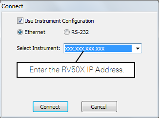
After the gateway and instruments are properly configured, you can connect to your instruments from any networked computer by entering the IP address for your gateway into the instrument software.
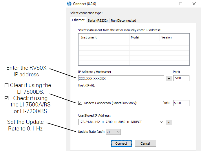
To connect with an LI-7200/RS or LI-7500A/RS using the gas analyzer interface software, launch the software, enter the gateway IP address, and click Connect.
To connect with an LI-7700, launch the software, enter the gateway IP address, and click Connect.