


Using the Trace Gas Sampling Kit
Authors: LI-COR, Inc.
Correspondence: envsupport@licor.com
Published: 2019
Instruments: LI-6400/XT, LI-8100A, Smart Chamber
Keywords: trace gas measurement, sampling kit
Abstract
The 8100-664 Trace Gas Sampling Kit is designed for use with the LI-8100A, Smart Chamber, and LI-6400/XT. This application note provides assembly instructions, usage guidelines, and data analysis considerations.
1 | What's What
The Trace Gas Sampling Kit includes all the components needed for use with all three instrument families. Some parts will get worn with use, may need to be discarded, and can be repurchased from LI-COR using the part numbers listed below.
| Description | Part # |
|---|---|
| Swagelok® T-fitting, modified | 9881-181 |
| Chamber exhaust tube (LI-6400/XT) | 9964-146 |
| Bev-A-Line® tubing | 222-01824 |
| Septa (6) | 300-08998 |
| ¼" plastic ferrules (6) | 300-05375 |
| Tubing with quick-connect fittings | 9981-178 |
| Flow restrictor | 301-17944 |
| Quick-connect plug | 300-07124 |
| Quick-connect coupler | 300-07125 |
2 | Collecting Samples from the Smart Chamber
Assembling the kit for use with the Smart Chamber is the same as the LI-8100A instructions presented above, except that it uses the flow restrictor and requires you to cut an additional length of tubing. The flow restrictor is placed in the length of tubing extending from the compression fitting arm with the Smart Chamber air in connector (the smaller of the two quick-connect fittings). Assemble the kit according to the following instructions.
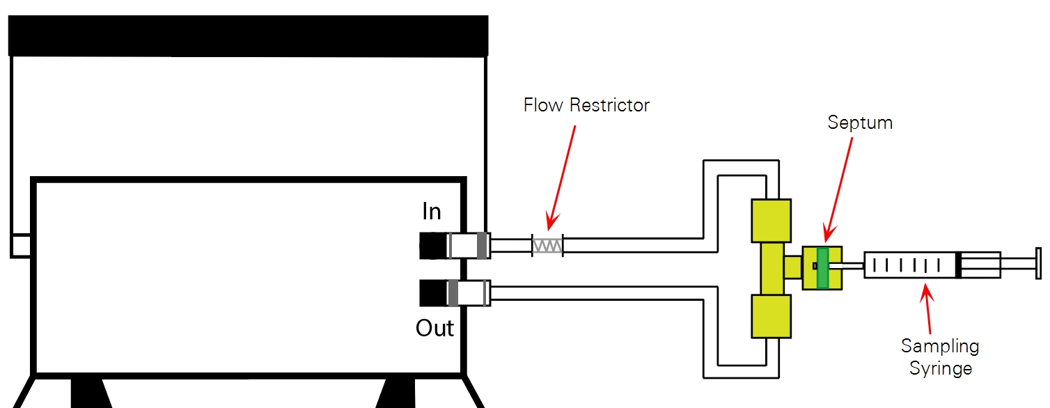
- Remove the brass nuts from the compression fitting.
- Locate the tubing with quick-connect fittings, two sets of ferrules, the flow restrictor, and cut an additional short (5-7 cm) length of tubing.
- Install a brass nut and one set of ferrules on the Smart Chamber air out connector segment (the larger of the two), and install the other nut and ferrules on one end of the additional length of tubing you cut. Note the orientation of the ferrules. The smaller, beveled piece must be installed first, facing the correct direction. When installed, the end of the tube should extend approximately 3 mm (1/8") beyond the ferrules.
- Insert the septum into the remaining nut. The septum has a self-sealing plastic coating on one side (identified by the glossy coating). For optimum sealing, install the septum with the glossy side facing the T-fitting.
- Assemble the T-fitting. Tighten the nuts, but do not over-tighten them, as this could create leaks around the septum and ferrules.
- Insert the flow restrictor into the bare tubing extending from the T-fitting.
- Attach the remaining length of tubing with air-in connector to the other end of the flow restrictor. Insert the barbs of the restrictor as deep as possible into the tubing.
- Attach the connectors to the Smart Chamber.

3 | Collecting Subsamples from the LI-8100A
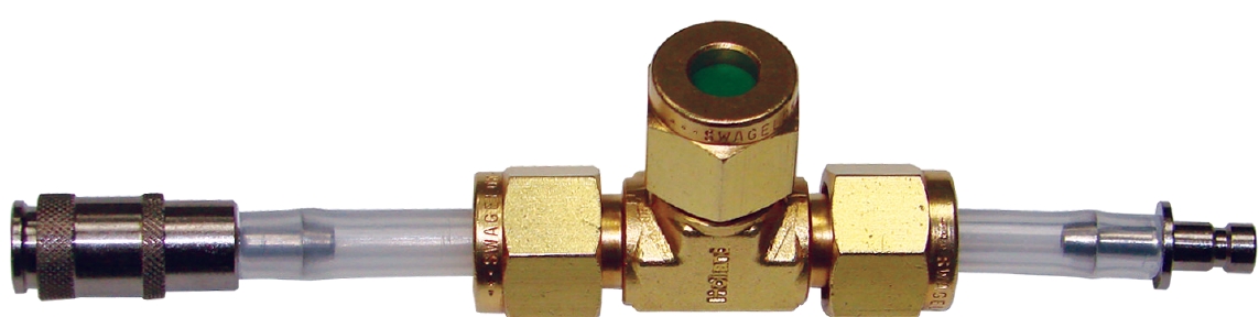
Assemble the Trace Gas Sampling Kit for the LI-8100A using the T-shaped compression fitting, two sets of ferrules, a septum, and tubing lengths with quick-connect fittings according to the following instructions.
- Remove the brass nuts from the compression fitting.
- Locate the tubing with quick-connect fittings and two sets of ferrules.
- Install a brass nut on each end of the tubing assemblies, and then install one set of ferrules on each assembly as shown.
- Note the orientation of the ferrules. The smaller, beveled piece must be installed first, facing the correct direction. When installed, the end of the tube should extend approximately 3 mm (1/8") beyond the ferrules.
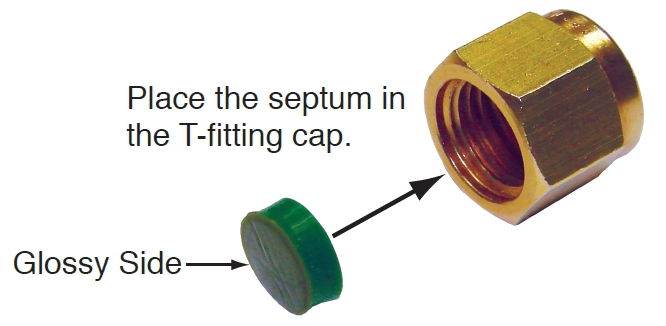
- Insert the septum into the remaining nut.
- The septum has a self-sealing plastic coating on one side (identified by the glossy coating). For optimum sealing, install the septum with the glossy side facing the T-fitting.
- Tighten the nuts on the T-fitting.
- Do not over-tighten them, as this could create leaks around the septum and ferrules.
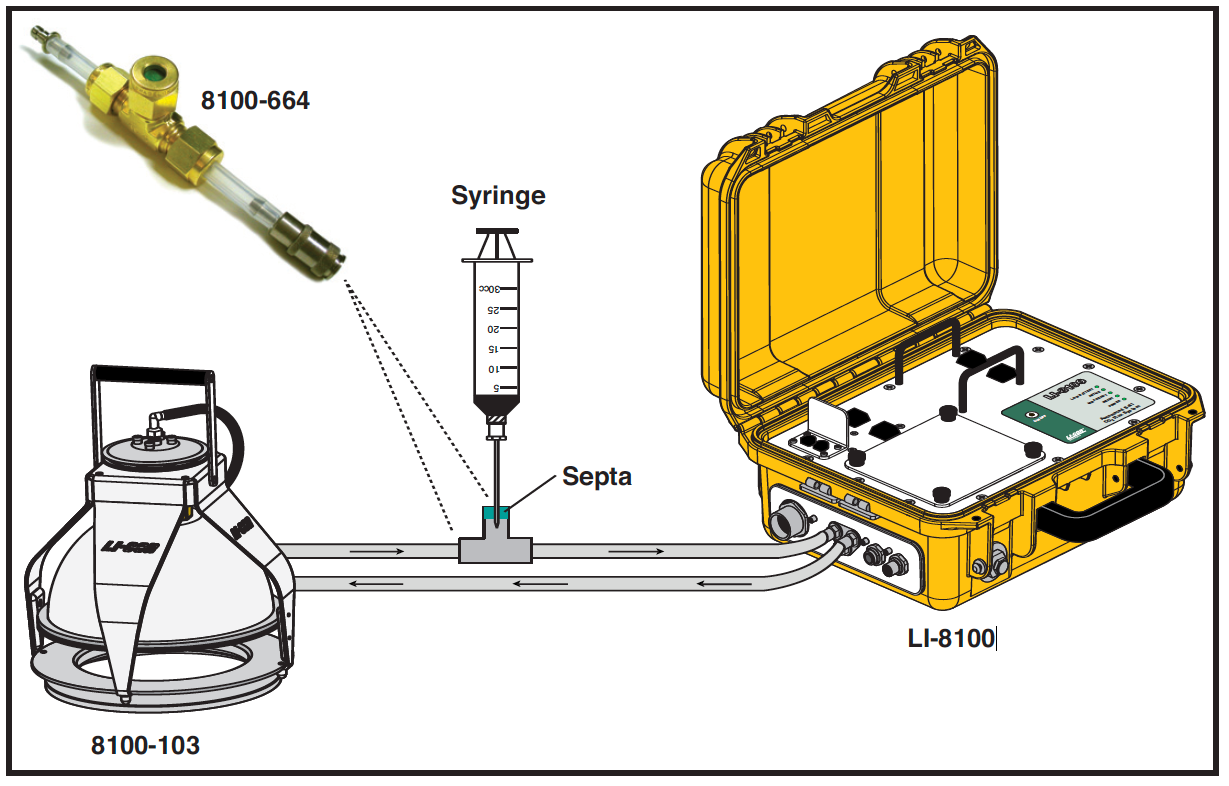
- Install the assembly in line between the LI-8100/A and the flux chamber.
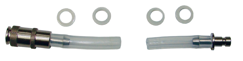
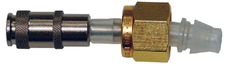
4 | Collecting Subsamples from the LI-6400/XT
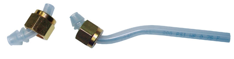
For use with the LI-6400/XT, assemble the Trace Gas Sampling Kit with the compression fitting, ferrules, a septum, and the lower chamber exhaust tubes according to the following instructions.
- Remove the nuts from the compression fitting.
- Locate the lower chamber exhaust tubes for the LI-6400/XT (two pieces, shown in step 3), and two sets of ferrules.
- Install a brass nut on each of the tubes and install one set of ferrules on each tube, as shown. Note the orientation of the ferrules. The smaller, beveled piece must be installed first, facing the correct direction. When installed, the end of the tube should extend approximately 3 mm (1/8") beyond the ferrules.
- Insert the septum into the remaining nut. The septum has a self-sealing plastic coating on one side (identified by the glossy coating). For optimum sealing, install the septum with the glossy side facing the T-fitting.
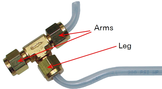
- Assemble the T-fitting with the septum-containing nut on one "arm" of the fitting, and the short tube on the other "arm." Install the long tube on the "leg." Tighten the nuts, but do not over-tighten them, as this could create leaks around the septum and ferrules.
- Install the assembled kit in place of the standard lower chamber exhaust tube. The ends of the tubes can be enlarged slightly with a pair of needle-nose pliers (or similar tool) to facilitate installation on the exhaust port hose barbs of the LI-6400/XT.
5 | Measurement Programming and Data Analysis
The Trace Gas Sampling Kit allows for small samples of air to measured from an air stream for estimating the flux of trace gases such as methane (CH4), ammonia (NH3), nitrous oxide (N2O), isotopic species, etc. The concentration of the gas species for those collected air samples can be subsequently analyzed with gas chromatography or mass-spectroscopy methods in a laboratory. The flux of the gas species can be estimated based on the rate of change of the gas species concentration inside the chamber and from information on other required variables, which can be obtained from the output file from the LI-8100A, LI-6400/XT, or Smart Chamber.
5.1 | Observation Length
A 2-minute observation length is adequate for soil CO2 flux measurements, but for other trace gases, the observation length may need to be much longer due to their low flux rates. The observation length of the LI-8100A, LI-6400/XT, or Smart Chamber can be set to any value. The appropriate observation length depends on how many trace gas samples are required and the time interval between them. Five to six samples during a period of 30 minutes may be sufficient for good curve fitting. The first air sample must not be taken until at least 20 seconds after the chamber is closed. Our experience suggests that good mixing in the system may not be established before 20 seconds have elapsed. If this air sampling method is used with a LI-8150 Multiplexer configuration, the first air sample should be taken at least 30 seconds after the chamber is closed.
5.2 | System Volume Considerations
It is important to note that the Trace Gas Sampling Kit adds a small amount additional volume to your system. In most cases, this added volume is negligible. If you are using the kit with a LI-8100A system or LI-6400/XT, you should not need to make any changes. If you are using the kit with a Smart Chamber, however, you will need to manually calculate the added volume and enter this into the user interface software when programming your measurements.
100 cm (1 meter) of 1/4" OD (outer diameter; 1/8" inner diameter) Bev-A-Line® tubing adds 7.9 cm3 of additional system volume, or 0.079 cm3 of added volume per cm of tubing. Measure your tubing and use these numbers to calculate the total amount of added volume (ignore the volume added by the Swagelok® fitting). Instructions for programming this added volume into your measurements are presented in the Smart Chamber manual.
Since the Trace Gas Sampling Kit is used with closed systems, removing air samples from the system will cause an error in the soil trace gas flux estimation. However, the error is negligible for a few small, discrete samples removed from the chamber during flux measurements, as the following analysis demonstrates.
For a CO2 flux measurement with a chamber volume of 5 liters, removing a 10 cm3 air sample from the chamber will create a very minor change in chamber CO2 concentration. If we assume the chamber headspace has a CO2 concentration of 450 μmol mol-1 and the removed air is refilled with ambient air having a CO2 concentration of 370 μmol mol-1, the chamber CO2 concentration will decrease by only 0.16 μmol mol-1 to 449.84 μmol mol-1.
1

Our experience suggests that removing a few small air samples during a measurement will therefore have a negligible effect on flux measurements.
5.3 | Data Processing
Depending on the behavior and shape of the time series data, the rate of change of the trace gas concentration (∂S/∂t) inside the chamber can be estimated with either a linear regression or an exponential curve fit as described in the LI-8100 User Manual, or e.g. de Mello and Hines (1994). If using an exponential curve fit, we suggest you estimate ∂S/∂t at t = 0, considering t = 0 as the time when the first trace gas sample was taken. After obtaining ∂S/∂t, the flux is then calculated using the following equation:
2
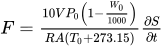
where W0 is the initial water vapor mole fraction (mmol mol-1), T0 is initial air temperature (°C). V is total system volume (cm3), P0 is the initial pressure (kPa), A is soil surface area (cm2), R is the gas constant (8.314 Pa m3 K-1mol-1). See the LI-8100A or Smart Chamber manual for further explanation.
After downloading a data file onto a computer, values for variables To, Po, Wo, V, and A can be conveniently obtained using SoilFluxPro Software. These variables are labeled as IV Tcham, IV Pressure, IV H2O, Vtotal, and Area. Tcham, IV Pressure, and IV H2O are in the group of Measured Variables. Vtotal and Area can also be exported into a text file for the flux calculation.
If the units for trace gas concentration are μmol mol-1 or ppm, then the final units for flux will be μmol m-2 s-1. If the units are nmol mol-1 or ppb, then flux will have the units of nmol m-2 s-1.
6 | References
| 1 | de Mello, W. Z., Hines, M. E., 1994. Application of static and dynamic enclosures for determining dimethyl sulfide and carbonyl sulfide exchange in Sphagnum peatlands: Implications for the magnitude and direction of flux. Journal of Geophysical Research, 99: 14,601- 14,607. |